This has been long overdue. In this blog post I will explain why a leaf spine model achieves the best scale model for a overlay network. I was recently on the #packetpushers podcast in the design and build show for BGP within the data center. We talked about why BGP is the best that we currently have for building a leaf spine infrastructure. I am big into VMware’s NSX but this sort of topology would be able to relate to any overlay model using the same principles. This will be a rather large post with the following technologies
1.)Leaf Spine architecture
a.)Spine layer
b.)Leaf layer
c.)Physical links
d.)East West bandwidth
2.)BGP
a.)BGP Peerings
b.)ECMP
c.)AS Numbering
d.)Community Strings
e.)Dynamic Peering
f.)AS-Override
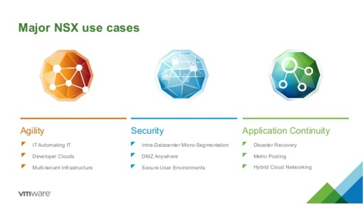
3.)NSX
a.)NSX edge router placement
b.)VTEP Communication
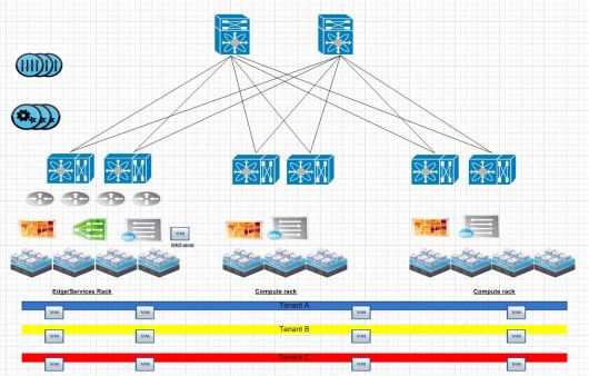
Here is your typical Leaf Spine infrastructure.
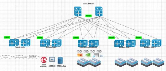
Spine Layer
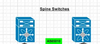
A common misconception here is that the spine switches have to be linked together. This is due to the prior ways of thinking with first hop redundancy protocols.Each connection from leaf to spine is a point to point layer 3 routed link. Spine switches are never connected together. As their soul purpose is to provide east west connectivity for leaf switches. So any traffic that egresses a leaf switch should simply pick via some ECMP method of landing on either spine to reach another leaf switch. Spine switches are very similar to “P” routers in a MPLS design. Each spine is also within the same BGP AS#.
Leaf switches
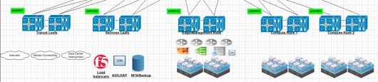
Each Leaf switch has its own purpose in this environment. Starting from left to right. The transit leafs provide connectivity to anything leaving the environment. When traffic egresses an environment typically we would send it to either another data center,internets or some sort of vendor connectivity or public/private cloud.
Services leaf in a design is generally where you put your external services. This can be a mixture of bare metal and virtual devices. I would suggest putting load balancers,AD/LDAP and any type of IP storage in this environment. Typically load balancers use source nat to have traffic ingress back through the load balancer after leaving a VM. In the future I will experiment more with hardware based VTEPs.
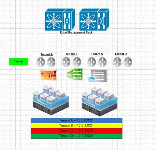
Edge/Management rack is for connectivity for our NSX or overlay networks. This is where our NSX routers peer via BGP with the top of rack switches and provide connectivity for all of our compute subnets.
Compute racks. Once we have our edge rack connected this is where we put all of our compute racks. So our clusters where have ESXi hosts running our Web,APP and DB cluster related VM’s.
The physical links within this infrastructure from leaf to spine have to be the same speed. So if you built your environment for 40GB/s links and 100GB/s came out the week after and is the new hotness you are stuck at 40GB/s. BGP is a distance vector protocol or what I would like to call a “Glorified next hop collector” Bandwidth is not taken into consideration. So a 40GB link is the same as a 100GB link. Do not worry I will explain why you can scale out more spines and it should not matter!
East-West traffic is the largest driving purpose for a leaf spine infrastructure. Lets take 2 VM’s across two different leaf switches for example.
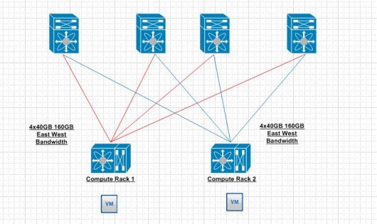
I only included one leaf switch on each compute rack for simplicity. As the drawing shows each VM to reach each other will land on a leaf switch. That leaf switch has 160GB of bandwidth to reach the other leaf switch. This seams like overkill at the moment but once you start layering a lot of web,app and db like applications thousands per different rack this makes a lot of sense. So getting back to our previous demonstration with physical link nodes if we find that we need to add more bandwidth there is nothing stopping anyone from adding another spine and one more 40GB link for an additional bandwidth. Most implementations I have experienced use the trident T2 which typically uses 48 10GB ports and 4 40GB ports. So 4 spines is the most I have seen at the moment.
BGP
Why BGP?
BGP historically has been given a bad reputation when it comes to convergence as the timers are slower and it was harder to use than your usual IGP that a network person could turn on within a few lines of CLI.. eww CLI!
OSPF is really not a applicable choice in this design as it is typically really difficult to filter with OSPF. EIGRP is our of the question to due it being proprietary.
BGP has made vast improvements in the protocol. It is enterprise ready. BGP is has quicker timers and we can make it dynamic now.
The peerings in a BGP leaf spine architecture are rather easy. iBGP between each leaf switches and eBGP between each leaf to spine connection. ECMP is rather vital in this topology as BGP by default DOES NOT leverage multiple links in a ECMP fashion. So generally it has to be turned on.
Community strings are vital. In the past network people have used prefix-list,access-list and route-maps to control traffic leaving a routing protocol. They still have their uses’s today but generally traffic leaving each environment should have a community string that matches its BGP AS. So for example if compute rack 1 uses 65004 it should use a community string of 65004:100. What works out really well for advertising subnets in the environment dynamically is leveraging the transit switches to to aggregate all of the community strings into one large community string for outbound advertisements to other data centers so it is dynamic. Today trying to use prefix-lists to control traffic that potentially touch a large amount of routers is less than ideal. If filtering is necessary on the edge routers that is about the only place I would apply prefix-lists to filter traffic.
Dynamic BGP
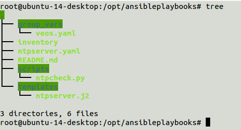
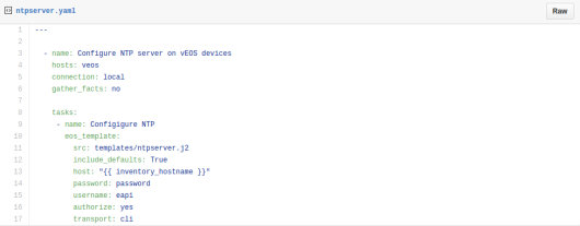
The first I heard about this was 2-3 years ago with MPLS routers. Cisco has moved this technology in all of their latest releases. I have also tested this with Arista switches. The idea is that you have a subnet you use for BGP for virtual routers. Lets say it is 10.10.27.0/24 and all of your NSX edge routers are located on that subnet within the same BGP AS you can dynamically bring up BGP peers on that network. I like this as there is no need to add neighbors or make a physical switch change.
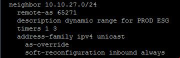
So any new virtual routers within the 10.10.27.0/24 network talking to the physical switch in this scenario will automatically peer with the physical switch. Now here is the tricky part. If you are using multiple tenants within the same physical infrastructure and they need to talk between each other as-override is needed. However, everything should just follow the default route that is advertised. I do this just in case a default route is lost.
NSX
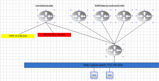
NSX or a hypervisor based overlay is what really scales in this environment. In our edge rack we place our NSX edge routers that peer with the physical network. These routers advertise our address space where our VM’s live. Since NSX 6.1.x days they support ECMP. Since their latest release now in 6.2.x NSX supports the use of seeing BGP AS paths within a given route which was not there prior.
The compute racks are what make the east west VM to VM connectivity possible. Within NSX each hypervisor terminates a tunnel known as VXLAN from one hypervisor to another to overlay layer 2 segments.
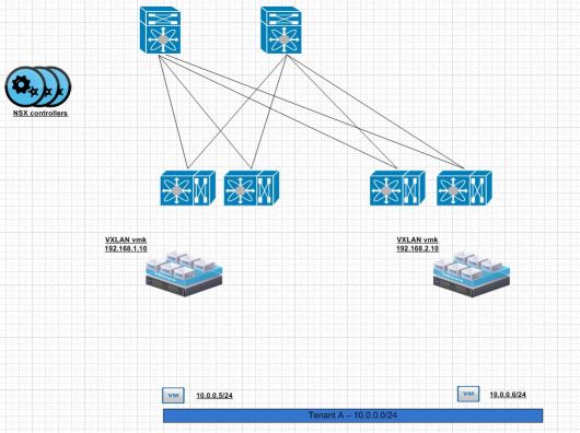
I have written about this before. The idea here is that the communication is from VXLAN vmk or VTEP. The outer part of the VXLAN packet will contain the source destination VTEP/VXLAN vmk interface. The inner part of the encapsulated packet will contain the 10.0.0.5/24 talking with the 10.0.0.6/24 for example.
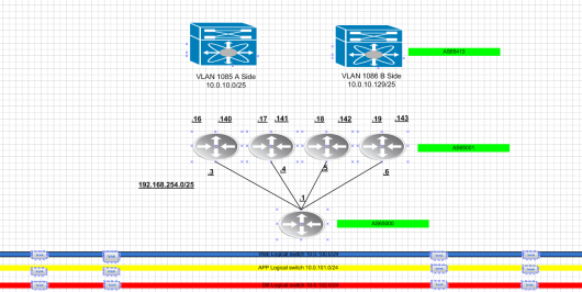
The broad idea here is that each network that is related to VTEPs needs advertised into BGP. So from edge/management to any of the computer cluster will use the VTEP network. So it needs advertised properly. All of the data plane traffic should be VXLAN and use those following segments. The end result should look like the following.